 Multiple Choice Questions
An ideal choke draws a current of 8 A when connected to an AC supply of 100 V, 50 Hz. A pure resistor draws a current of 10 A when connected to the same source. The ideal choke and the resistor are connected in series and then connected to the AC source of 150 V, 40 Hz. The current in the circuit becomes
8 A
18 A
10 A
In a series resonant R-L-C circuit, the voltage across R is 100 V and the value of R = 1000 Ω. The capacitance of the capacitor is 2 × 10⁻⁶ F, angular frequency of AC is 200 rad s-1. Then the potential difference across the inductance coil is
100 V
40 V
250 V
400 V
In an AC circuit, V and I are given by V = 150 sin (150 t) volt and amp. The power dissipated in the circuit is
106 W
150 W
5625 W
Zero
In the series L-C-R circuit shown, the impedance is

200 Ω
100 Ω
300 Ω
500 Ω
D.
500 Ω
A transformer works on the principle of
self-induction
electrical inertia
mutual induction
magnetic effect of the electrical current
A resistor of 500 Ω, an inductance of 0.5 H are in series with an AC, which is given by . The power factor of the combination is
0.6
0.5
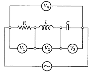
An ideal resistance R, ideal inductance L, ideal capacitance C and AC voltmeters ,V1, V3 and V4 are connected to an AC sources as shown in figure. At resonance

reading in V2 = reading in V3
reading in V3 =reading in V1
reading in V1 = reading in V2
reading in V2 = reading in V4
For a transformer, the turns ratio is 3 and its efficiency IS 0.75. The current flowing in the primary coil is 2 A and the voltage applied to it is 100 V. Then the voltage and the current flowing in the secondary coil are respectively
150 V, 1.5 A
300 V, 0.5 A
300 V, 1.5 A
150 V, 0.5 A
In R-L-C seres circut, the potential differences across each element is 20 V. Now the value of the resistance alone is doubled, then P.D. across R, L and C respectively
20 V, 10 V, 10 V
20 V, 20 V, 20 V
20 V, 40 V, 40 V
10 V, 20 V, 20 V
A series combination of resistor (R), capacitor (C) is connected to an A.C. source of angular frequency. Keeping the voltage same, if the frequency is changed to ω/3, the current becomes half of the original current. Then the ratio of the capacitive reactance and resistance at the former frequency is
