 Multiple Choice Questions
When 5V potential difference is applied across a wire of length 0.1 m, the drift speed of electrons is 2.5 × 10⁻⁴ ms–1. If the electron density in the wire is 8 × 1028 m–3, the resistivity of the material is close to:
1.6 x 10⁻⁸Ωm
1.6 x 10⁻⁷Ωm
1.6 x 10⁻⁶Ωm
1.6 x 10⁻⁶Ωm
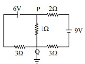
In the circuit shown, the current in the 1Ω resistor is:
1.3 A from P to Q
0 A
0.13 A, from Q to P
0.13 A, from P to Q
C.
0.13 A, from Q to P
Connect Point Q to ground and by applying Kirchhoff's laws
consider the grounded circuit as shown below,
Applying Kirchhoff's law at point Q,
Incoming current at Q = outgoing current from Q
Thus, current in the 1Ω resistance is 0.13 A, from Q to P
Two long current carrying thin wires, both with current I, are held by insulating threads of length L and are in equilibrium as shown in the figure, with threads making an angle ‘θ’ with the vertical. If wires have mass λ per unit length then the value of I is: (g = gravitational acceleration)


An inductor (L = 0.03 H) and a resistor (R = 0.15 kΩ) are connected in series to a battery of 15V EMF in a circuit shown. The key K1 has been kept closed for a long time. Then at t = 0, K1 is opened and key K2 is closed simultaneously. At t = 1 ms, the current in the circuit will be:
( )
)
100 mA
67 mA
6.7 mA
6.7 mA
The current voltage relation of the diode is given by I = e(1000V/T-1) mA, where the applied voltage V is in volt and the temperature T is in kelvin. If a student makes an error measuring ± 0.01V while measuring the current of 5mA at 300K, what will be the error in the value of current in mA?
0.2 mA
0.02 mA
05 mA
05 mA
The coercivity of a small magnet where the ferromagnet gets demagnetized is 3 x 10³Am-1.The current required to be passed in a solenoid of length 10 cm and number of turns 100, so that the magnet gets demagnetized when inside the solenoid, is
30 mA
60 mA
3 A
3 A
In the circuit shown here, the point C is kept connected to point A till the current flowing through the circuit becomes constant. Afterwards, suddenly point C is disconnected from point A and connected to point B at time t= 0. Ratio of the voltage across resistance and the inductor at t = L/R will be equal to 

1
-1
-1
The supply voltage to a room is 120 V. The resistance of the lead wires is 6 Ω. A 60 W bulb is already switched on. What is the decrease of voltage across the bulb, when a 240 W heater is switched on in parallel to the bulb?
zero
2.9V
13.3 V
13.3 V
This question has statement I and statement II. Of the four choices given after the statements, choose the one that best describes the two statements.
Statement- I: Higher the range, greater is the resistance of ammeter.
Statement- II: To increase the range of ammeter, additional shunt needs to be used across it.
Statement – I is true, Statement – II is true, Statement – II is the correct explanation of statement- I.
Statement – I is true, Statement – II is true, Statement – II is not the correct explanation of Statement–I.
Statement – I is true, statement – II is false.
Statement – I is true, statement – II is false.
The magnetic field in a travelling electromagnetic wave has a peak value of 20 nT. The peak value of electric field strength is :
3 V/m
6 V/m
9 V/m
9 V/m
