 Multiple Choice Questions
Two heating coils of resistances 10 Ω and 20 Ω are connected in parallel and connected to a battery of emf 12 V and internal resistance 1 Ω. The power consumed by them are in the ratio
1 : 4
1 : 3
2 : 1
4 : 1
Of the following graphs, the one that correctly represents the I-V characteristics of a 'Ohmic device' is

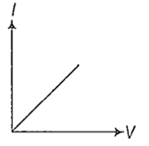
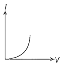

The working of magnetic braking of trains is based on
eddy current
pulsating current
alternating current
steady current
A cylindrical conductor of diameter 0.1 mm carries a current of 90 mA. The current density (in Am-2) is (π ≈ 3)
12 × 107
3 × 10⁶
6 × 10⁶
2.4 × 10⁷
A straight wire of length 50 cm carrying a current of 2.5 A is suspended in mid-air by a uniform magnetic field of 0.5 T (as shown in figure). The mass of the wire is (g = 10 ms-2)

250 gm
125 gm
62.5 gm
100 gm
In meter bridge experiment, with a standard resistance in the right gap and a resistance coil dipped in water (in a beaker) in the left gap, the balancing length obtained is 'l'. If the temperature of water is increased, the new balancing
< 1
> 1
= 0
= 1
The value of I in the figure shown below is
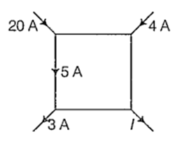
21 A
4 A
8 A
19 A
A.
21 A
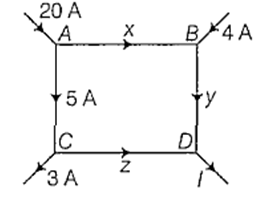
At junction A,
20 = 5 + x
x = 20 − 5 = 15 A
At junction B,
4 + x = y
4 + 15 = y
y = 19 A
At junction C,
5 = 3 + z
z = 5 − 3 = 2 A
Now, network is shown by the following diagram
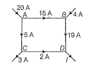
At junction D,
I = 19 + 2
I = 21 A
