 Multiple Choice Questions
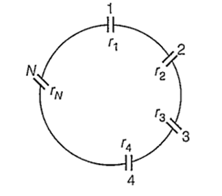
A group of N cells whose emf varies directly with the internal resistance as per the equation EN = 1.5 rN are connected as shown in the figure above. The current I in the circuit is
5.1 A
0.51 A
1.5 A
0.15 A
The temperature coefficient of resistance of a wire is 0.00125/°C. Its resistance is 1 ohm at 300 K. Its resistance will be 2 ohm at
1127 K
1400 K
1154 K
1100 K
A potentiometer has uniform potential gradient. The specific resistance of the material of the potentiometer wire is 10-7 ohm-metre and the current passing through it is 0.1 ampere, cross-section of the wire is 10-6 m2. The potential gradient along the potentiometer wire is
10-6 V/m
10-4 V/m
10-8 V/m
10-2 V/m
A fuse wire with radius 1 mm blows at 1.5 ampere. The radius of the fuse wire of the same material to blow at 3A will be
31/4 mm
41/3 mm
31/2 mm
21/3 mm
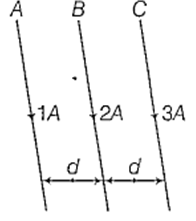
Three long straight wires A, B and C are carrying currents as shown in figure. Then the resultant force on B is directed
perpendicular to the plane of paper and outward
perpendicular to the plane of paper and inward
towards A
towards C
An unknown resistance R1 is connected in series with a resistance of 10 Ω. This combination is connected to one gap of a metre bridge while a resistance R2 is connected in the other gap. The balance point is at 50 cm. Now, when the 10 Ω resistance is removed the balance point shifts to 40 cm. The value of R1 is (in ohms)
20
10
60
40
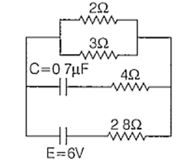
In the circuit shown, the internal resistance of the cell is negligible. The steady state current in the 2 Ω resistor is
0.6 A
1.2 A
0.9 A
1.5 A
C.
0.9 A
In the steady state, no current flows through the branch containing the capacitor. So, the equivalent circuit will be of the form as shown below
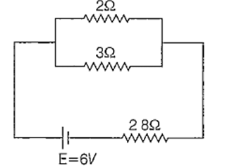
The effective resistance of the circuit is
The current through the circuit is
Let current i1 flows through 2 Ω resistance.
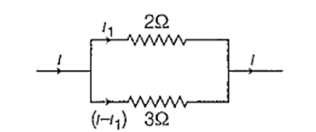
∴ 2 × i1 = (i − i1) × 3
⇒ 2i1 = (1.5 − i1) × 3
⇒ 2i1 = 4.5 − 3i1
⇒ 5i1 = 4.5
∴ i1 = 0.9 A
Two electnc bulbs A and B are rated as 60 W and 100 W. They are connected in parallel to the same source. Then
B draws more current than A
currents drawn are in the ratio of their resistances
both draw the same current
A draws more current than B
A wire has a resistance of 6 Ω. It is cut into two parts and both half values are connected in parallel. The new resistance is
3 Ω
6 Ω
12 Ω
1.5 Ω
The current in a simple series circuit is 5.0 amp. When an additional resistance of 2.0 ohms is inserted, the current drops to 4.0 amp. The original resistance of the circuit in ohms was
1.25
8
10
20
