 Short Answer Type
A sinusoidal voltage e = e0 Sin (wt) is fed to a common emitter amplifier. Draw neatly labelled diagrams to show:
(i) Signal voltage
(ii) Output voltage of the amplifier.

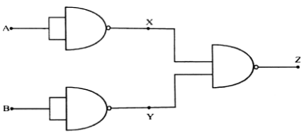
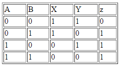
The truth table for the logic gate is as shown below:

1. When A and B are 0, we get X and Y as 1 and 1 respectively. When 1 and 1 is given as input we get output Z as 0.
2. When A is 0 and B is 1, we get X as 1 and Y as 0. We get Z as 1.
3. When A is 1 and B is 0, X is 0 and Y is 1 and Z is 1.
4. When A and B both are 1, then X and Y both will be zero and Z will be 1.
 Long Answer Type
Electrons, initially at rest, are passed through a potential difference of 2 kV. Calculate their:
(i) Final velocity and
(ii) de Broglie wavelength.
