 Short Answer Type
An isolated 16 μF parallel plate air capacitor has a potential differences of 1000 V (Figure 5 a). A dielectric slab having relative permittivity (i.e. dielectric constant) = 5 is introduced to fill the space between the two plates com pletely. (Figure 5 b). Calculate:
(i) The new capacitance of the capacitor.
(ii) The new potential differences between the two plates of the capacitor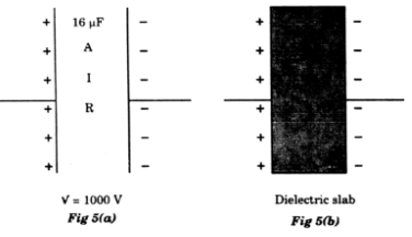
An electron revolves around the nucleus of hydrogen atom in a circular orbit of radius 5 x 10-11 m. Calculate
(i) Intensity of electric field of the nucleus at the position of the electron.
(ii) Electrostatic potential energy of the hydrogen nucleus and electron system.
In the circuit shown below, PQ is a uniform metallic wire of length 4 m and resistance 20 Ω. Battery B has an emf of 10V and internal resistance of 1 Ω. J is a jockey or slide contact. Resistance of the ammeter and connecting wires is negligible.
(i) When the jockey J does not touch the wire PQ, what is the reading of ammeter A?
(ii) Where should the jockey J be pressed on the wire PQ so that the galvanometer G shows no deflection?
 is kept in two uniform and perpendicular magnetic fields
  as shown below:
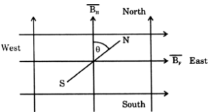
(i) What is the effect of each of the magnetic fields on the needle?
(ii) When the needle is in equilibrium, obtain an expression for an angle θ made by the needle with  in terms
  of only.
 at a point M which lies exactly midway between PQ and RS.
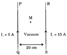
The cause of induced emf may be explained on the basis of Lorentz force.
We know that if a charge q moves with velocity v in a magnetic field of strength B, making an angle θ, then magnetic Lorentz force is given by,
F = q v B sin θ
If v and B are mutually perpendicular, then θ = 90°
F = q v B sin 90 = q v B
The direction of this force is perpendicular to both v and B and is given by Fleming’s left hand rule.
Suppose a thin conducting rod PQ is placed on to parallel metallic rails CD and MN in a magnetic field of strength B.
The direction of magnetic field B is perpendicular to the plane of paper, downward.
In fig below it is represented by cross (x) marks. 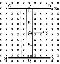
Suppose the rod is moving with velocity v, perpendicular to its own length, towards the right.
We know that a metallic conductors contain free electrons, which can move within the metal.
As charge on electron, q = -e, therefore, each electron experiences a magnetic Lorentz force, Fm = e v B, whose direction, according to Fleming’s left hand rule, will be from P to Q.
Thus the electron are displaced from end P towards end Q. Consequently the end P of rod becomes positively charged and end Q negatively charged. Thus a potential difference is produced between the ends of the conductor. This is the induced emf.
Due to induced.emf, an electric field is produced in the conducting rod.
The strength of this electric field,
E = V/ l
And its direction is from (+) to (-) charge, i.e. from P to Q.
The force on a free electron due to this electric field, Fe = e E
The direction of this force is from Q to P is opposite to that of electric field.
Thus, the emf produced opposes the motion of electrons caused due to Lorentz force. This is in accordance with Lenz‘s law.
As the number of electrons at end Q become more and more, the magnitude of electric force Fe goes on increasing, and a stage comes when electric force Be and magnetic force Fm become equal and opposite.
In this situation the potential difference produced across the ends of the rod becomes constant. In this condition
Fe = Fm
eE = evB or
E = Bv
The potential difference produced, V = E l = B v l


 Switch


