With the help of a labelled diagram, explain the principle, construction and working of an electric motor. What is the function of a split ring in an electric motor?
Electric Motor:
We describe here a d.c. motor which operates on direct current obtained from a battery.
Principle: An electric motor works on the principle that a current carrying conductor placed in a magnetic field experiences a force, the direction of force is given by Fleming’s left hand rule.
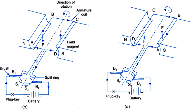
Construction: As shown in Fig.an electric motor consists of the following main parts:
1. Field magnet: It is a strong horse shoe type magnet with concave poles.
2. Armature: It is a rectangular coil ABCD having a large number of turns of thin insulated copper wire wound over a soft iron core. The armature is placed between the poles of the field magnet and it can be rotated about an axis perpendicular to the magnetic field lines.
 Fig. An electric d.c. motor
3. Split ring commutator: It consists of a cylindrical metal ring split into two halves S
1and S
2. The two ends A and D of the armature coil are connected to the split rings S
1 and S
2 respectively. As the coil rotates, the split rings also rotate about the same axis of rotation. The function of the split ring commutator is to reverse the direction of current in the coil after every half rotation.
4. Brushes: Two graphite or flexible metal rods maintain a sliding contact with split rings S
1 and S
2, alternately.
5. Battery: A battery of few cells is connected to the brushes. The current from the battery flows to the armature coil through the brushes and the split rings.
Working: Initially, suppose the plane of the coil is horizontal. The split ring S
1 touches the brush B
1 and split ring S
2 touches the brush B
2. The current in coil flows in the direction ABCD, as shown in Fig.(a)
Clearly, the currents in arms AB and CD are in opposite directions. On applying Fleming’s left hand rule for the direction of force on a current-carrying conductor in a magnetic field, we find that the force acting on arm AB pushes it downwards while the force acting on the arm CD pushes it upwards. Thus the armature coil alongwith the axle rotates anticlockwise. After half a rotation, as shown in Fig.(b), the split ring comes in contact with brush B
2 and S
2 in contact with brush B
1. Therefore, the current in the coil gets reversed and flows along the path DCBA. A device that reverses the direction of flow of current through a circuit is called commutator. In electric motors, the split ring acts as a commutator. Thus the arm AB is now pushed up and the arm CD is pushed down. Therefore, the coil and the axle rotate half a turn more in the same direction. The reversing of the current is repeated at each half rotation, giving rise to a continuous rotation of the coil and to the axle.
1801 Views

