 Multiple Choice Questions
An L-C-R series circuit with a resistance of 100 Ω is connected to 200 V (AC source) and angular frequency 300 rad/s. When only the capacitor is removed, then the current lags behind the voltage by 60°. When only the inductor is removed the current leads the voltage by 60°. The average power dissipated in original L-C-R circuit is
50 W
100 W
200 W
400 W
The concentric, conducting spherical shells X, Y and Z with radii r, 2r and 3r, respectively. X and Z are connected by a conducting wire and Y is uniformly charged to charge Q as shown in figure. Charges on shells X and Z will be

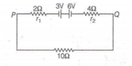
Two batteries of emf 3V and 6 V with internal resistances 2 Ω and 4 Ω are connected in a circuit with resistance of 10 Ω as shown in figure. The current and potential difference between the points P and Q are
The charges on two spheres are + 7 µC and -5C respectively. They experience a force F. If each of them is given an additional charge of -2 µC, then the new force of attraction will
F
2F
A rod made up of metal is 1.2 m long and 0.8 cm in diameter. Its resistance is 3.5 x 10⁻³ Ω. Another disc made of the same metal is 2.0 cm in diameter and 1.25 mm thick. What is the resistance between the round faces of the disc?
1.35x 10⁻⁸ Ω
2.70 x 10⁻⁷ Ω
5.82 × 10⁻⁷ Ω
8.10 × 10⁻⁵ Ω
A body is moving along a rough horizontal surface with an initial velocity of 10 ms-1. If the body comes to rest after travelling a distance of 12m, then the coefficient of sliding friction will be
0.5
0.2
0.4
0.6
A circular current carrying coil has a radius R. The distance from the centre of the coil, on the axis, where B will be of its value at the centre of the coil is
2 R
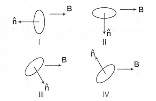
A current carrying loop is placed in a uniform magnetic field in four different orientations I, II, III and IV as shown in figure. Arrange them in decreasing order of potential energy
l > lll> ll > lV
l > ll > lll > lV
l > lV > ll > lll
lll > lV > l > ll
In the given figure, the capacitors C1, C3, C4, C5 have a capacitance 4 µF each. If the capacitor C2 has a capacitance 10 μF, then effective capacitance between A and B will be 
2 μF
6 μF
4 μF
8 μF


 Switch


